ZDA-4320RH:
Handshake Connection ASI / SDI / STM-1 Data Amplifiers. | ||
FEATURES:
|
||
GENERAL:
|
||
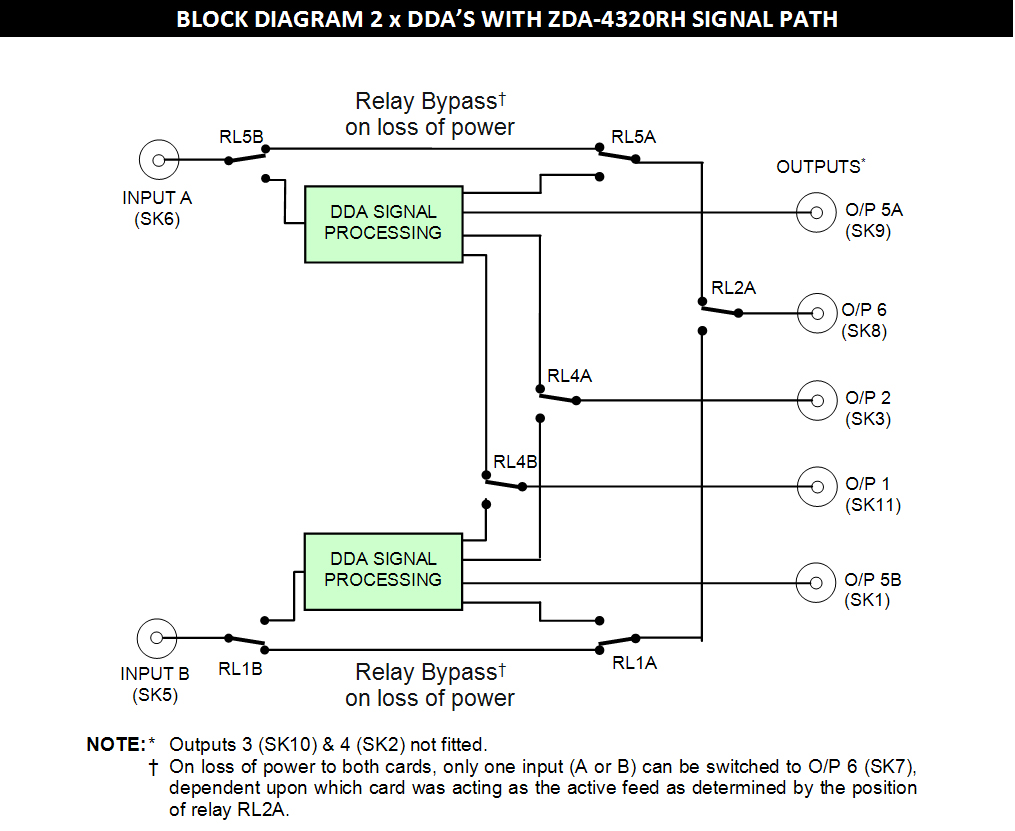
The DDA-4320 is an ASI / SDI / STM-1 data distribution amplifier that incorporates a protection
switching facility for five switching outputs to a standby module when a fault is detected. | ||
|
||
TECHNICAL SPECIFICATIONS:
|
||
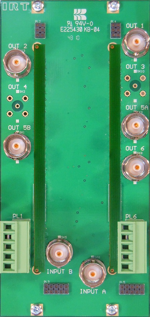
Inputs: |
|
Number |
2 [A (SK6) & B (SK5)]. |
Type |
ASI/SDI, or STM-1 (dependent on DDA-4320 configuration). |
Impedance |
75 Ω, BNC. |
Return loss |
15dB 5 MHz to 270 MHz. |
Outputs: |
|
Number |
3 switched [outputs 1 (SK11), 2 (SK3) & 6 (SK8)]* and |
2 fixed [outputs 5A (SK9) & 5B (SK1)]. |
|
(Relay bypass of active input (SK5 or SK6) to output (SK8) on loss of power or removal of both cards). |
|
Type |
ASI/SDI, or STM-1 (dependent on DDA-4320 configuration). |
Impedance |
75 Ω, BNC. |
Return loss |
15dB 5 MHz to 270 MHz. |
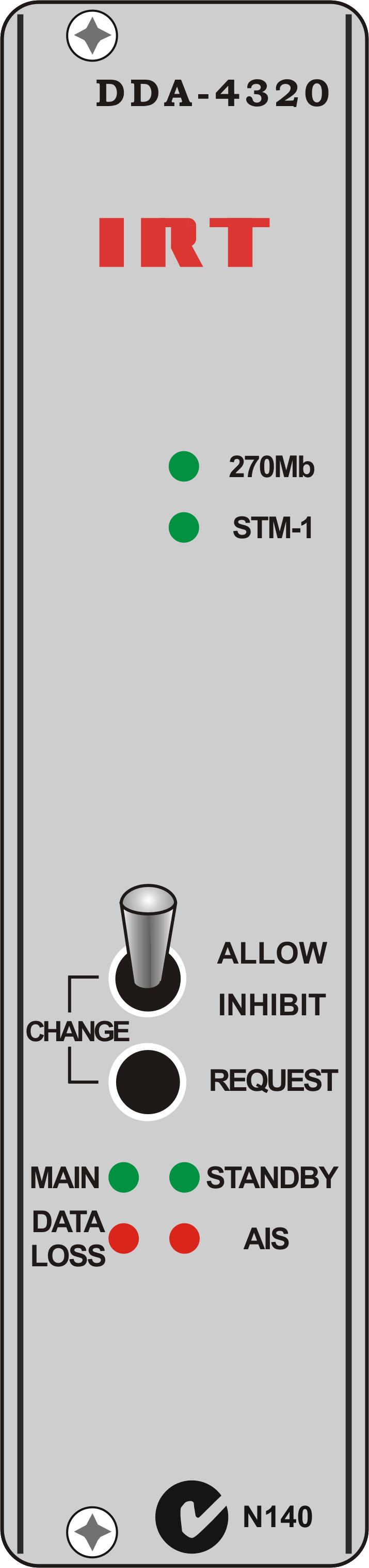
Controls & alarms: |
|
Connector |
2 x 5-pin Phoenix style (A & B). |
Pin 1 |
Tally - a connection to ground indicates that the corresponding module is the 'Main' path. |
2 |
External changeover request - connecting to ground will make this module 'Main'. |
3 |
Input Alarm - an open circuit indicates that there is no input signal present, input signal does not match the set
signal type, or AIS detected in STM-1 data. |
4 |
Power Fail - an open circuit indicates that power to the module has failed. |
5 |
Ground. |
NOTE: * |
Outputs 3 (SK10) and 4 (SK2) not fitted. |
|
Corresponding front panel toggle switch of module must be in the 'Change Allow' position. |
|
The non-alarm state is a connection to ground via a FET relay. |
Changeover logic: |
A changeover to the companion module will occur under any of the following conditions: |
Loss of input signal or input signal does not match the set signal type; |
|
Loss of power; and |
|
Manual changeover request either by the DDA-4320 front panel switches, externally via a
connection to ground on the Changeover Request pin on the ZDA 4320RH rear assembly, or via SNMP. |
In all of the above cases switching will occur only if the companion module is free of the same defects.
The manual changeover requests (local and remote) require that the changeover inhibit switch is not activated on the module currently acting as the Standby unit.
|
Priority logic: |
The priority switching in normal mode follows non reverting logic which dictates: |
In the event of failure of the Main DDA-4320, the Standby DDA-4320 will assume control of the switched outputs
and become Main causing the failed path DDA 4320 to become Standby. This implies that when the failed path is restored it will remain as Standby and not become
Main unless either a failure of Main occurs or a manual changeover is requested. |
Power on reset: |
When power is applied to the pair, the module which was last operating as Main will remain as Main. |
When power is applied to a pair for the first time it may be necessary to request a manual changeover to force the desired module to become Main. |
 |
Due to our policy of continuing development, these specifications are subject to change without notice.
|