ZDA-4300RH:
Handshake Connection E1, E3 & DS3 Data Amplifiers. | ||
FEATURES:
|
||
GENERAL:
|
||
IRT produces a range of data distribution amplifiers that operate at the E1 (2.048Mb/s),
E3 (34.368Mb/s) & DS3 (44.736Mb/s) rates in accordance with G.703. All incorporate a protection switching facility for the switching in of signals from a standby module when a fault is detected. | ||
|
||
TECHNICAL SPECIFICATIONS:
|
||
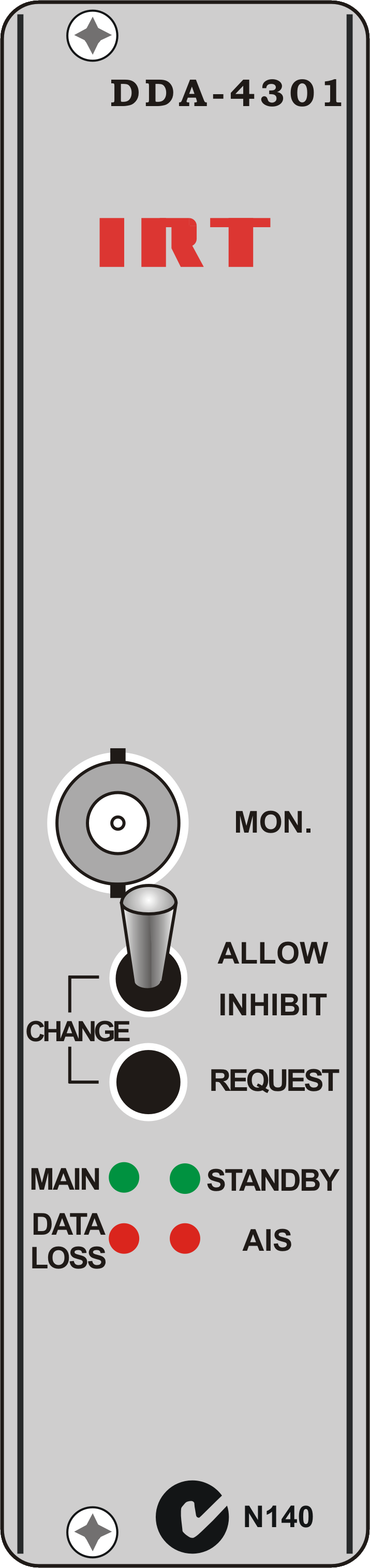
Controls & alarms: |
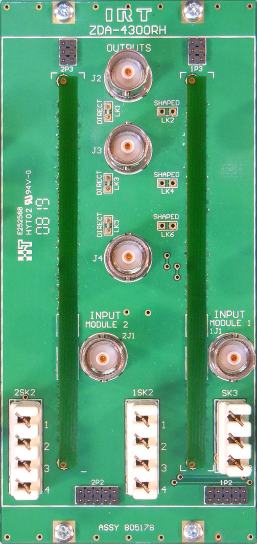
Outputs: |
|
Bypass |
Contact closure to ground if power has failed. |
General Alarm |
Contact closure to ground if:- |
a. Data Loss is detected OR |
|
b. AIS is detected AND the AIS disable is not set. |
|
AIS detection is defined as at least 2048 consecutive data "1"s. |
|
Data Loss is defined as less than 120 data "1"s in 512 34 Mbit clock periods. |
|
In Service (Main) Path Indication |
Transistor switch to ground if card is active (if DA version is equipped). |
Connectors: |
|
Data: |
BNC. |
Alarm: |
Krone LSA plus. |
In Service (Main) Path: |
Krone LSA plus. |
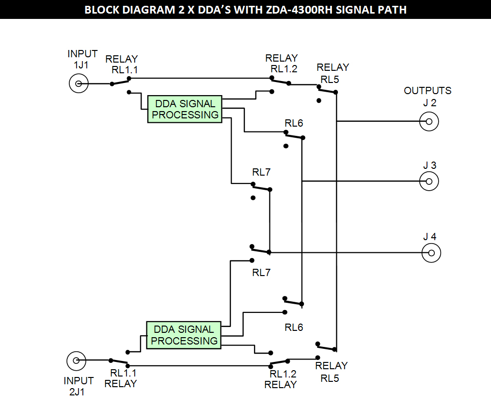
Changeover logic: |
A changeover to the companion module will occur under any of the following conditions: |
Loss of input signal |
|
AIS detection alarm (provided AIS is not disabled) |
|
Loss of power |
|
In all of the above cases switching will only occur if: |
Companion module is able to provide an output free of the same defects and |
|
Changeover inhibit switch is not activated on either module. |
Priority logic: |
The priority switching in normal mode follows non reverting logic which dictates: |
In the event of failure of Main then Standby
DDA will assume control and become Main causing the failed path DDA to become Standby. |
This implies that when the failed path is restored that it will remain
as Standby and not become Main unless either a failure of Main occurs or a manual changeover is requested. |
Power on reset:
When power is applied to the pair, the power on reset signal will set the module which was last enabled as Main as Main and the other module will be forced to act as Reserve. When power is applied to a pair for the first time it may be necessary to force the desired module to become Main by pressing the Change Request button on the front panel of the desired module. The Main module will be indicated by the In Service LED being lit on the front panel. |
 |
Due to our policy of continuing development, these specifications are subject to change without notice.
|