IRT-6630-DTR:
3G/HD/SD-SDI/ASI Fibre Optic Transceiver | ||
FEATURES:
|
||
GENERAL:
|
||
The IRT-6630-DTR is a transmit/receive (transceiver) module designed principally for use as
a serial data fibre optic transmission link for 3G-SDI, HD-SDI or SD SDI applications conforming to SMPTE standards 424M, 292M and 259M-C using
9/125 µm single mode fibre. This enables the use of space saving fibre optic cable for reliable transmission of digital video signals over
lengths greater than can be achieved with coaxial cable. |
NOTE: |
1 |
27dB path loss at 3G. Typically >30dB at HD and SD. Fitted with APD detector. |
2 |
With WDM option fitted for combined use on a single fibre, optical path loss is reduced by approximately 2dB. |
|
3 |
With WDM option fitted, when operating as a pair, one IRT-6630-DTR must be fitted with
a 1310nm laser and the other a 1550nm laser. |
|
||
TECHNICAL SPECIFICATIONS:
|
||
Transmitter: |
|
Input serial data signal |
2.97 Gb/s (3G-SDI) to SMPTE 424M; 1.485 Gb/s (HD-SDI) to SMPTE 292M; 270 Mb/s (SD-SDI) to SMPTE 259M-C and DVB-ASI. |
Input Impedance |
75 Ω. |
Input Return Loss |
> 15 dB 5 MHz to 1.5 GHz; > 10 dB 1.5 GHz to 2.97 GHz. |
Automatic Cable Compensation |
> 100 m at 2.97 Gb/s (3G-SDI) with Belden 1694A (typ. 110m);; > 100 m at 1.485 Gb/s (HD-SDI) with Belden 1694A (typ. 160m); > 250 m at 270 Mb/s (SD-SDI/ASI) with Belden 8281 (typ. >300m). |
Input Connector |
2 x BNC on rear panel, with I/P 1 taking priority & I/P 2 automatically switching in on loss of I/P 1. |
Output Connector |
1 x BNC (OUT 1) on rear panel, link selectable Tx input monitor, or nil if set as a second Rx output. |
Receiver: |
|
Number of Outputs |
2 data reclocked, AC coupled. |
Output Level |
800 mV ± 10%. |
Output Impedance |
75 Ω. |
Output Return Loss |
> 15 dB 5 MHz to 1.5 GHz; > 10 dB 1.5 GHz to 2.97 GHz. |
Output Rise and Fall Time |
< 135 ps at 2.97 Gb/s and 1.485 Gb/s; > 0.4 ns and < 1.5 ns at 270 Mb/s. |
Intrinsic Jitter |
< 0.3 UI at 2.97 Gb/s reclocked; < 0.2 UI at 1.485 Gb/s reclocked; < 0.1 UI at 270 Mb/s reclocked. |
Output Connector |
2 x BNC on rear assembly, or 1 x BNC if OUT 1 has been link selected as an input monitor. |
Optical: |
|
Optical Output |
0 dBm +4.5/-0 dB CWDM DFB laser. |
Optical Input |
APD detector, -9 to -27 dBm input level at 3G-SDI, typically < -30 dBm at HD/SD-SDI. |
Available Wavelengths |
1310nm or 1550nm. Other wavelengths available upon request. |
Optical Path Loss4,5 |
9 to 27 dB at 3G-SDI, typically >30 dB at HD/SD-SDI, APD detector. (Optical path loss = Laser O/P power - Detector I/P power) |
Optical Fibre |
Designed for use with 9/125 µm single mode fibre. |
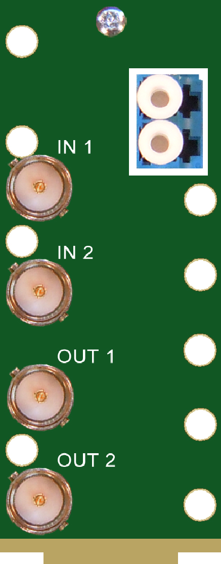
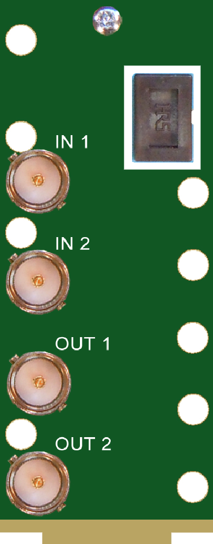
Optical Connector |
2 x LC/PC (standard) on rear - direct connection to main card, 1 Tx and 1 Rx; or 1 x SC/PC (standard) with WDM option fitted. |
Power Requirements: |
|
Voltage |
+ 12 Vdc. |
Power consumption |
< 5VA. |
Other: |
|
Temperature range |
0 - 50°C ambient. |
Mechanical |
Suitable for mounting in an openGear® 2RU rack chassis. |
Dimensions (openGear® standard) |
33.6 mm x 2U x 325 mm. |
Supplied accessories |
Rear connector assembly. |
Optional Accessories |
On-board 1310/1550nm WDM6 combiner. |
Ordering |
IRT-6630-DTR |
IRT-6630-DTR, programmed with DashBoard control; |
WDM order codes |
IRT-6630-DTR/1310/WDM & IRT-6630-DTR/1550/WDM. |
|
NOTE: |
4 |
Typical values based using DFB laser. Optical attenuator supplied for when
optical path loss is less than 9dB for APD detector. |
|
5 |
With WDM option fitted for combined use on a single fibre, optical path loss
is reduced by approximately 2dB. |
||
6 |
With WDM module fitted, when operating as a pair, one IRT-6630-DTR must be fitted
with a 1310nm laser and the other a 1550nm laser. |
 |
IRT-6630-DTR
IRT-6630-DTR/WDM |
Due to our policy of continuing development, these specifications are subject to change without notice.
|
