DTR-1000:
Multi-Channel 3G/HD/SD/ASI + Gigabit Ethernet Fibre Optic Link | ||
FEATURES:
|
||
GENERAL:
|
||
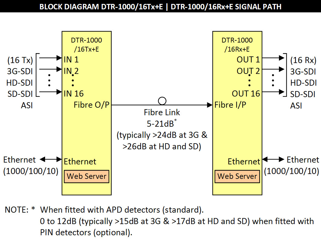
The DTR-1000 is a multi-channel transmitter / receiver unit designed principally for use as an
up to sixteen serial data + Ethernet fibre optic transmission link on a single fibre for 3G-SDI,
HD-SDI or SD-SDI applications conforming to SMPTE standards 424M, 292M and 259M-C
using 9/125 µm single mode fibre. |
 |
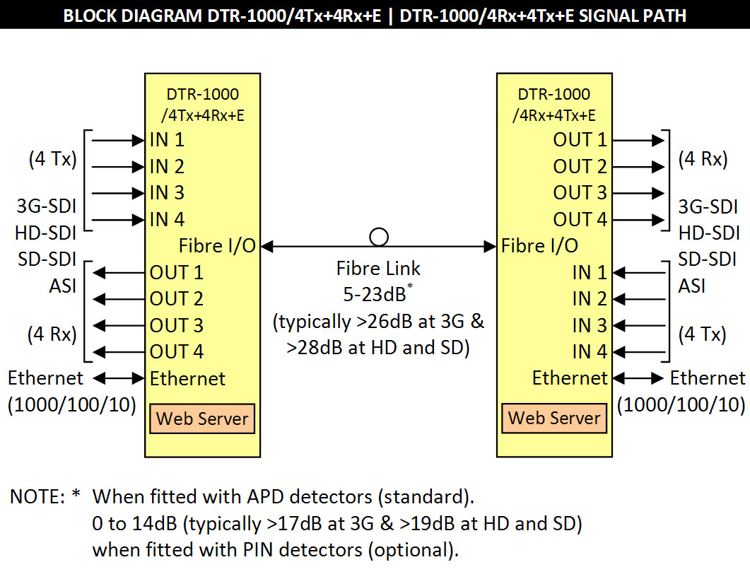
BLOCK DIAGRAMS:
|
||
|
||
|
||
|
||
|
||
|
||
TECHNICAL SPECIFICATIONS:
|
||
Transmitter Mode: |
|
Input Serial Data Signal |
2.97 Gb/s (3G-SDI) to SMPTE 424M; 1.485 Gb/s (HD-SDI) to SMPTE 292M; 270 Mb/s (SD-SDI) to SMPTE 259M-C and DVB-ASI. |
Input Impedance |
75 Ω. |
Input Return Loss |
> 15 dB 5 MHz to 1.5 GHz; > 10 dB 1.5 GHz to 2.97 GHz. |
Automatic Cable Compensation |
> 100 m at 2.97 Gb/s (3G-SDI) with Belden 1694A (typ. 110m);; > 140 m at 1.485 Gb/s (HD-SDI) with Belden 1694A (typ. 160m); > 250 m at 270 Mb/s (SD-SDI/ASI) with Belden 8281 (typ. >300m). |
Input Connector |
Up to 16 x BNC on rear panel, 1 per channel, dependent upon model chosen. |
Receiver Mode: |
|
Number of Outputs |
1 per channel, data reclocked, AC coupled. |
Output Level |
800 mV ± 10%. |
Output Impedance |
75 Ω. |
Output Return Loss |
> 15 dB 5 MHz to 1.5 GHz; > 10 dB 1.5 GHz to 2.97 GHz. |
Output Rise and Fall Time |
< 135 ps at 2.97 Gb/s and 1.485 Gb/s; > 0.4 ns and < 1.5 ns at 270 Mb/s. |
Intrinsic Jitter |
< 0.3 UI at 2.97 Gb/s reclocked; < 0.2 UI at 1.485 Gb/s reclocked; < 0.1 UI at 270 Mb/s reclocked. |
Output Connector |
Up to 16 x BNC on rear panel, 1 per channel, dependent upon model chosen. |
Ethernet: |
|
Type |
Standard IEEE 802.3i, 802.3y & 802.3ab |
Data Rate |
10/100/1000 Mb/s, automatic. |
Maximum Frame Size |
10,240 bytes. |
Connector |
RJ-45. |
Optical: |
|
Optical Output |
0 dBm +4.5/-0 dB individual CWDM DFB laser. |
Optical Input (APD Standard) |
-5 to -21 dBm, typically < -24 dBm at 3G-SDI & < -26 dBm at HD/SD-SDI + Ethernet. |
(PIN Optional) |
0 to -12 dBm, typically < -15 dBm at 3G-SDI & < -17 dBm at HD/SD-SDI + Ethernet. |
Wavelengths |
18 x CWDM DFB lasers - 1270nm to 1610nm, 20nm spacing. |
Optical Path Loss2,3 |
5 to 21 dB, typically > 24 dB at 3G-SDI & > 26 dB at HD/SD-SDI, APD detectors; 0 to 12 dB, typically > 15 dB at 3G-SDI & > 17 dB at HD/SD-SDI, PIN detector. |
Optical Fibre |
Designed for use with 9/125 µm single mode fibre. |
Optical Connector |
1 x SC/PC (standard) on rear. |
Power Requirements: |
|
Voltage |
90 - 264 Vac and/or +12 Vdc. |
Power consumption |
< 40 VA. |
Other: |
|
Temperature range |
0 - 50°C ambient. |
Mechanical |
1 RU (482 mm x 44.5 mm) standard 19" rack frame; suitable for mounting in standard 19" racks. |
Dimensions |
482 x 44.5 x 310 mm. |
Ordering |
DTR-1000/16Tx+E |
DTR-1000 configured as a 16-channel transmitter only + Ethernet. |
DTR-1000/16Rx+E |
DTR-1000 configured as a 16-channel receiver only + Ethernet. |
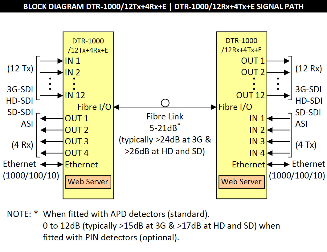
DTR-1000/12Tx+4Rx+E |
DTR-1000 configured as a 12-channel transmitter/4-channel receiver + Ethernet. |
DTR-1000/12Rx+4Tx+E |
DTR-1000 configured as a 12-channel receiver/4-channel transmitter + Ethernet. |
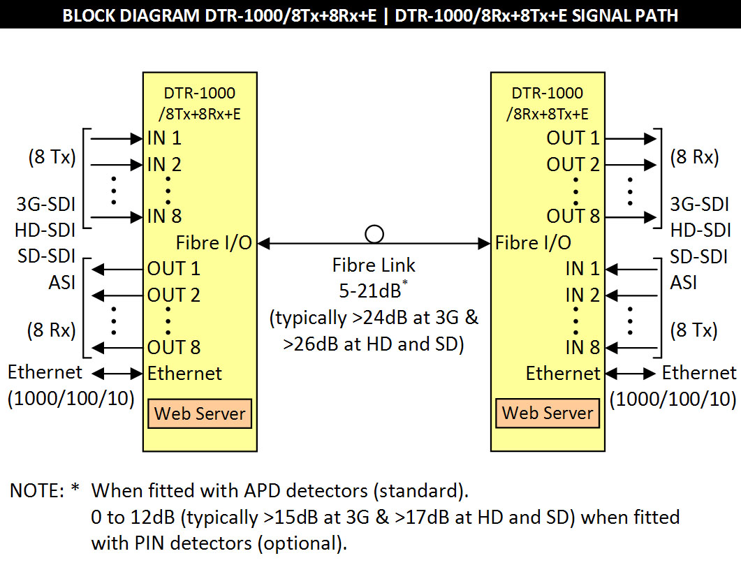
DTR-1000/8Tx+8Rx+E |
DTR-1000 configured as a 8-channel transmitter/8-channel receiver + Ethernet. |
DTR-1000/8Rx+8Tx+E |
DTR-1000 configured as a 8-channel receiver/8-channel transmitter + Ethernet. |
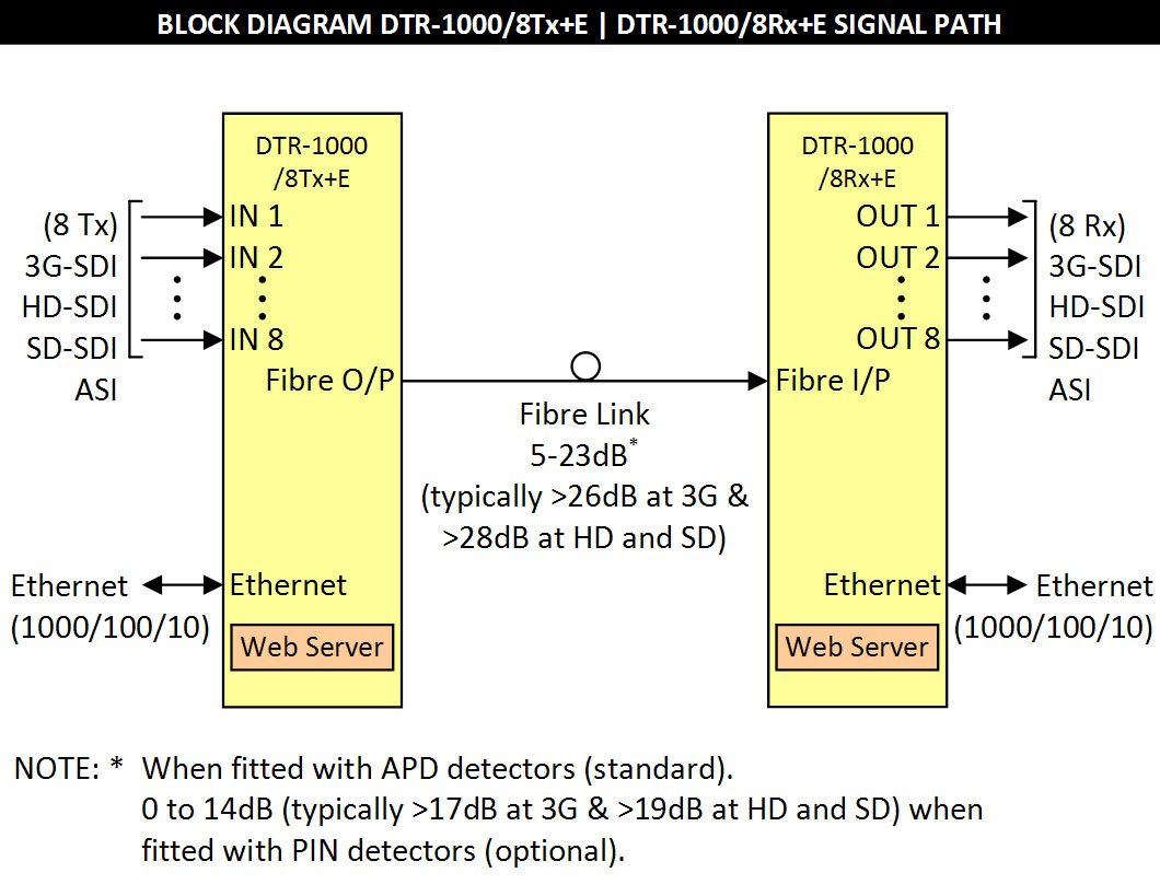
DTR-1000/8Tx+E |
DTR-1000 configured as a 8-channel transmitter only + Ethernet. |
DTR-1000/8Rx+E |
DTR-1000 configured as a 8-channel receiver only + Ethernet. |
DTR-1000/4Tx+4Rx+E |
DTR-1000 configured as a 4-channel transmitter/4-channel receiver + Ethernet. |
DTR-1000/4Rx+4Tx+E |
DTR-1000 configured as a 4-channel receiver/4-channel transmitter + Ethernet. |
NOTE: 2 |
Optical attenuator supplied for when optical path loss is less 5dB for APD detector. |
3 |
Add 2dB to optical path loss for 8Tx+E, 8Rx+E, 4Tx+4Rx+E and 4Rx+4Tx+E models. |
DTR-1000/16Tx+E Rear Panel Signal Connectors: |
 |
DTR-1000/16Rx+E Rear Panel Signal Connectors: |
 |
DTR-1000/12Tx+4Rx+E Rear Panel Signal Connectors: |
 |
DTR-1000/12Rx+4Tx+E Rear Panel Signal Connectors: |
 |
DTR-1000/8Tx+8Rx+E Rear Panel Signal Connectors: |
 |
DTR-1000/8Rx+8Tx+E Rear Panel Signal Connectors: |
 |
DTR-1000/8Tx+E Rear Panel Signal Connectors: |
 |
DTR-1000/8Rx+E Rear Panel Signal Connectors: |
 |
DTR-1000/4Tx+4Rx+E Rear Panel Signal Connectors: |
 |
DTR-1000/4Rx+4Tx+E Rear Panel Signal Connectors: |
 |
Due to our policy of continuing development, these specifications are subject to change without notice.
|