DDA-4010:
Single 1 In, 8 Out / Dual 1 In, 4 Out 3G/HD/SD/ASI | ||
FEATURES:
|
||
GENERAL:
|
||
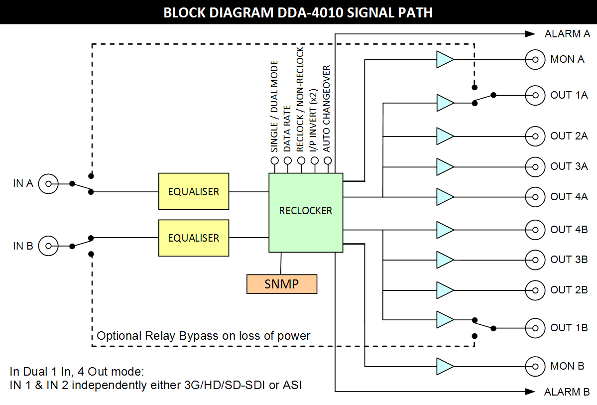
The DDA-4010 serial digital data distribution amplifier provides the user with a
single module to cover a wide range of distribution and monitoring functions for 3G/HD/ SD-SDI or ASI signals. | ||
|
||
TECHNICAL SPECIFICATIONS:
|
||
Inputs: |
|
Number |
2. |
Impedance |
75 Ω, BNC. |
Type
|
3G-SDI, HD-SDI, SD-SDI or ASI (to SMPTE 424M, 292M and 259M-C standards; and DVB-ASI standard). |
Return loss |
15dB 5 MHz to 1.485 GHz, |
10dB from 1.485 GHz to 2.97 GHz1. |
|
Equalisation Automatic |
100 m at 3G-SDI rate with Belden 1694A2, |
200 m at HD-SDI rate with Belden 16942,3, 120 m with Belden 82812,3, |
|
400 m at SD-SDI/ASI rate with Belden 16943, 300 m with Belden 82813,4. |
|
Outputs: |
|
Number |
8 (1 in, 8 out; or (2x) 2 in, 4 out), plus 2 front panel monitoring. |
Type |
Reclocked or non-reclocked, switch selectable. |
Level |
800 mV ± 10%. |
Impedance |
75 Ω, BNC. |
Return loss |
15dB 5 MHz to 1.485 GHz, |
10dB from 1.485 GHz to 2.97 GHz1. |
|
Performance: |
|
Reclocking |
Automatic or selectable for 3G-SDI, HD-SDI or SD-SDI / ASI operation. |
Rise time 3G/HD |
< 135 ps at 2.97 Gb/s and 1.485 Gb/s; |
SD |
> 0.4 ns and < 1.5 ns at 270 Mb/s. |
Intrinsic jitter |
< 0.3 UI at 2.97 Gb/s reclocked; |
< 0.2 UI at 1.485 Gb/s reclocked; |
|
< 0.1 UI at 270 Mb/s reclocked. |
|
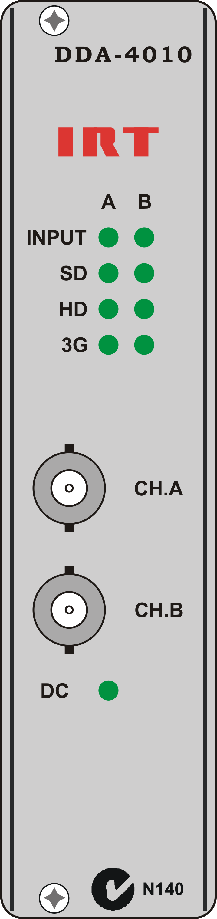
Indicators: |
|
DC |
LED (green) for module power. |
INPUT A |
LED (green) when signal present on channel A input (LED flashes if present but not active5). |
INPUT B |
LED (green) when signal present on channel B input (LED flashes if present but not active5). |
SD |
LED (green) x2 when SD-SDI or ASI signal present and locked to selected input on either A or B outputs. |
HD |
LED (green) x2 when HD-SDI signal present and locked to selected input on either A or B outputs. |
3G |
LED (green) x2 when 3G-SDI signal present and locked to selected input on either A or B outputs. |
Alarm Outputs: |
|
Alarm A |
A alarm switches to either open circuit or ground (link selectable)
via MOSFET relays on either loss of signal or incorrect signal rate on I/P A. |
Alarm B |
B alarm switches to either open circuit or ground (link selectable)
via MOSFET relays on either loss of signal or incorrect signal rate on I/P B. |
Power Requirements: |
|
Voltage |
28 Vac CT (14-0-14) or ±16 Vdc. |
Power consumption |
< 6VA. |
Other: |
|
Temperature range |
0 - 50°C ambient. |
Mechanical |
Suitable for mounting in IRT 19" rack chassis with input, output and power connections on the rear panel. |
Finish: Front panel |
Grey background, black lettering & red IRT logo. |
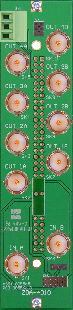
Rear Panel |
Detachable silk-screened PCB with direct mount connectors to Eurocard and external signals. |
Dimensions |
6 HP x 3 U x 220 mm IRT Eurocard. |
Standard |
Rear connector assembly with matching connector for alarm output. |
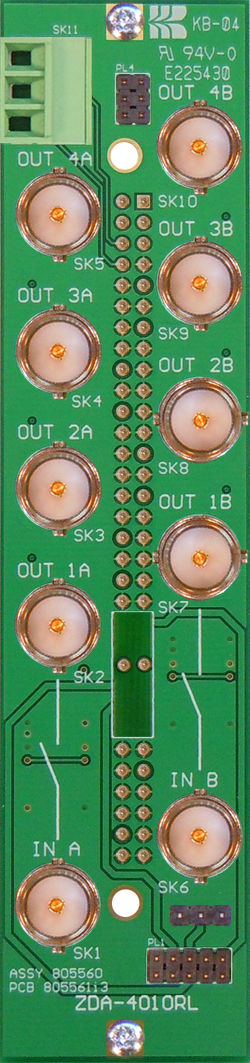
Optional |
ZDA-4010RL relay bypass rear assembly suitable for 3G-SDI1, HD-SDI and SD-SDI/ASI signals. |
NOTE: 1 |
Return loss reduced by a couple of dB at 3G rate with optional bypass relay. |
2 |
Reduces to ~ 50m with optional bypass relay rear assembly. |
3 |
If two inputs are being inputted, cable equalisation is limited to that of the higher rate. |
4 |
Reduces to ~ 70m when SW1-4 (I/P A), SW2-4 (I/P B) is ON. |
5 |
When automatic change-over function has been set. |
|
ZDA-4010 |
ZDA-4010RL |
|
Standard |
3G/HD/SD/ASI |
|
Rear Assembly |
Relay Bypass |
|
Rear Assembly |
Due to our policy of continuing development, these specifications are subject to change without notice.
|