AMS-4172:
3G/HD/SD-SDI, ASI, G.703, Video, Audio Relay Changeover Switch. | ||
FEATURES:
|
||
GENERAL:
|
||
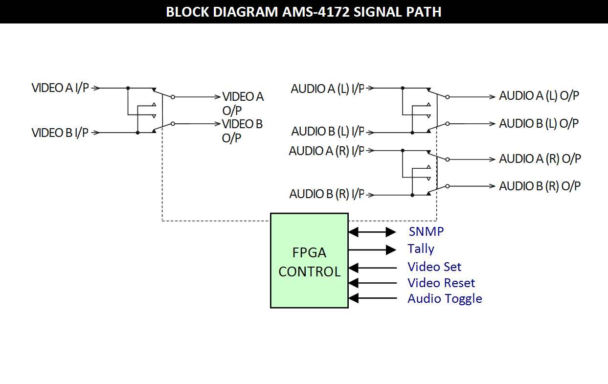
The AMS-4172 consists of one "video" and two "balanced audio" switches arranged as a changeover set with two inputs
and two outputs. No terminations are provided on the board allowing the switcher to be used in a wide variety of applications and with signals of various types and impedances. | ||
|
||
TECHNICAL SPECIFICATIONS:
|
||
Signal Inputs: |
|
Signal types |
3G-SDI/HD-SDI/SD-SDI/ASI/G.703/Video/unbalanced AES. |
Impedance |
Non-terminating, designed for 75 Ω use. |
Switching characteristic |
Magnetic latching 4 port changeover relay. |
Video crosstalk between channels |
< -75 dB to 10 MHz (measured input terminated by 75 Ω); |
| < -45 dB to 270 MHz; | |
| < -40 dB to 1.5 GHz; | |
| < -25 dB to 3.0 GHz. | |
Frequency response |
+0/-1.5 dB 0 Hz to 3.0 GHz. |
Audio/Low speed Data: |
|
Audio Crosstalk |
< -90 dB (20 Hz - 20 kHz, input terminated by 600 Ω). |
Control: |
|
Mode |
Momentary ground or open circuit, switch selectable. |
Gnd |
Pin 1. |
Audio Toggle |
Pin 2 (Standby / Main). |
Video Reset |
Pin 3 (Main). |
Video Set |
Pin 4 (Standby). |
NOTE: |
Separate Audio & Video controls, or |
Audio follows Video, switch selectable. |
|
Non-momentary contacts required in Toggle modes. |
|
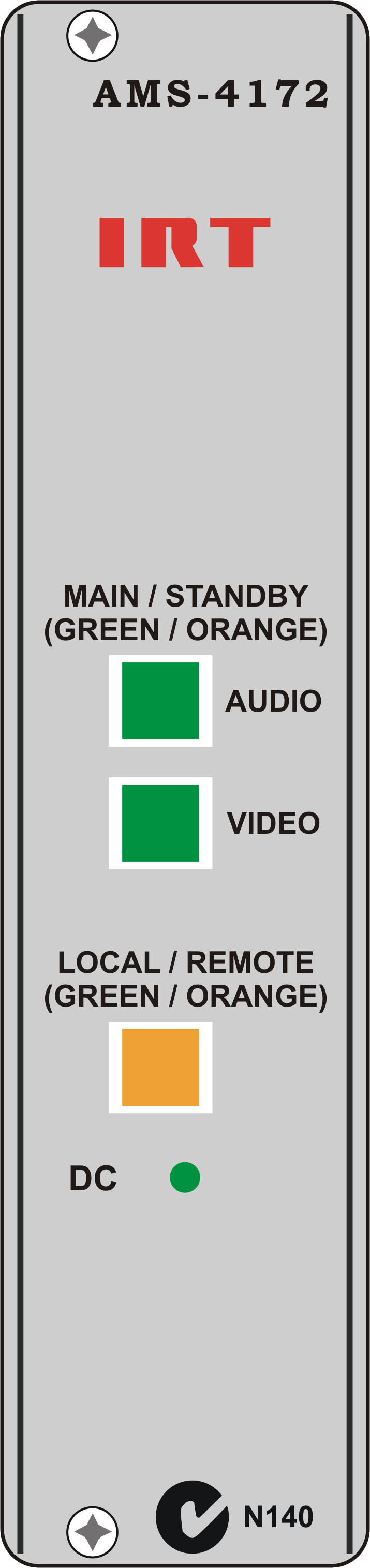
Front panel switches |
Momentary illuminated push button. |
Automatic remote default setting after several minutes. |
|
Tally |
Switch to Ground - Main; Switch to Open Circuit - Standby. |
Gnd |
Pin 1. |
Video Tally |
Pin 2. |
Audio Tally |
Pin 3. |
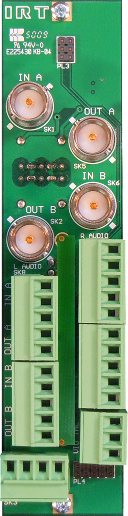
Connectors: |
|
Video |
BNC. |
Audio |
5 pin Phoenix pluggable screw block. |
Control |
4 pin Phoenix pluggable screw block. |
Tally |
3 pin Phoenix pluggable screw block. |
Relay: |
|
Contact rating |
30 Vdc - 0.5 A. |
Power Requirements: |
|
Voltage |
28 Vac CT (14-0-14) or ±16 Vdc. |
Power consumption |
< 1.5 VA. |
Other: |
|
Temperature range |
0 - 50°C ambient. |
Mechanical |
Suitable for mounting in IRT 19" rack chassis with input, output and power connections on the rear panel
(Note: Not compatible with pre-4000 series 3RU frames). |
Finish: Front panel |
Grey background, black lettering & red IRT logo. |
Rear assembly |
Detachable silk-screened PCB with direct mount connectors to Eurocard and external signals. |
Dimensions |
6 HP x 3 U x 220 mm IRT Eurocard. |
Supplied accessories |
Rear connector assembly with matching connectors for control input and tally outputs. |
NOTE: Main: |
IN A to OUT A, IN B to OUT B; |
Standby: |
IN A to OUT B, IN B to OUT A. |
|
Due to our policy of continuing development, these specifications are subject to change without notice.
|